TRACK CIRCUITS
The signalling system at DVR is based upon 'fail-safe' control. This includes interlocking which prevents the system allowing conflicting or dangerous moves to be made by trains. For example, a signal will not allow a train into a section if there is a train already occupying the section. One requirement of this interlocking is being able to determine where trains are on the track, and whether a particular part of the track is occupied by a train.
Track Sections
Every length of track in a signalled area is split up into logical sections called 'track sections' or 'blocks'. For example, on the main line, each track section is about 100m long. In this case, a signal is placed at the start of each track section to indicate whether the section ahead is 'occupied' or 'clear'. The signal will not allow a train to enter the section unless it is 'clear'. Another example is track section containing a set of points. About 1 to 5m of track going into and out of a set of points might be one track section. This section would therefore need to be 'clear' for the points to be changed.
Track Circuits
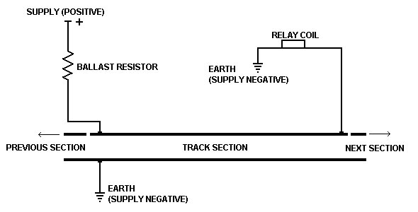
For the state of the track sections (clear or occupied) to be used to prevent or allow signals and points to operate, the state must be detected electrically. This is done using 'track circuits'. The requirement of the track circuit is that an electrical relay (electrically controlled switch) be on if the track section is clear, or off if the section is occupied. This relay allows other electrical interlocking systems to 'know' whether that track section is occupied. To allow the relay to be turned on requires a power supply. At DVR we use a 12V DC supply. Essentially, the circuit works by applying a voltage across the two rails in a track section. This voltage powers the relay. If a train enters the section, the wheels and axles make an electrical connection between the two rails and the voltage drops to near zero, turning off the relay. The relay will not turn on again until the last axle of the train has left the section - regardless of the train length. Obviously, this system will only work when wooden sleepers are used, as metal sleepers would also make an electrical connection between the two rails, preventing the circuit from working. The circuit is shown below:
It's All About Current Flow
For the state of the track sections (clear or occupied) to be used to prevent or allow signals and points to operate, the state must be detected electrically. This is done using 'track circuits'. The requirement of the track circuit is that an electrical relay (electrically controlled switch) be on if the track section is clear, or off if the section is occupied. This relay allows other
electrical interlocking systems to 'know' whether that track section is occupied. To allow the relay to be turned on requires a power supply. At DVR we use a 12V DC supply. Essentially, the circuit works by applying a voltage across the two rails in a track section. This voltage powers the relay. If a train enters the section, the wheels and axles make an electrical connection
between the two rails and the voltage drops to near zero, turning off the relay. The relay will not turn on again until the last axle of the train has left the section - regardless of the train length. Obviously, this system will only work when wooden sleepers are used, as metal sleepers would also make an electrical connection between the two rails, preventing the circuit from working.
The circuit is shown below:
The purpose of the ballast resistor is to limit the amount of current flowing when the section is occupied. Without the resistor, the circuit becomes almost a dead short across the supply and the supply would fail. The resistor is usually a high power (10W) variable resistor. The reason we use variable resistors is so that the resistance can be set high enough to keep current flow low, but low enough to allow enough current for the relay to turn on. Each track section has its own ballast resistor and relay. The power supply is used by more than one track circuit - the positive connects to many ballast resistors and the negative connects to the continuous earth rail, and to each relay.
Use of Track Relays
Electrical detection of track occupancy allows for a very functional signalling system. It allows signals to work automatically, it prevents points from changing under trains, it allows the signaller to know exactly where their trains are, and adds to the realism to the system.
Signal Control
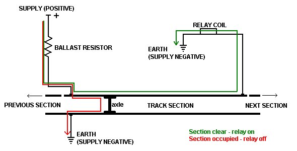
For example, the following is a circuit for an automatic signal (simplified). The main components of the circuit are:
- The signal. It has one red light and one green. It is automatic - meaning it is not controlled by a signal box.
- The track relay. As explained above, the relay turns on when the track is clear, and off when the track is occupied. The relay contains a set of changeover contacts (NO and NC).
When the track is clear, the track relay is on and the NO contacts connect the power to the green light. If the track is occupied then the relay is off and the NC contacts turn on the red light.
This signal works purely off the track relay and isn't controlled by a signalman.
The following is a circuit for a controlled signal (simplified). The main components of the circuit are:
- The signal. It has one red light and one green.
- The track relay.
- The signal lever. This might be a switch on a panel in a signal box. It allows controlling of the signal by the signalman.
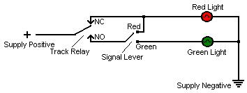
The idea of the circuit is that when the track is clear, and the signal lever is set to the green position, the signal goes green. If either the track is occupied or the signal lever is set to red, then the signal will be red. The signalperson cannot set the signal to green if the track is occupied.
Points Control
The following circuit (simplified) is used to control a set of electric points. The actual design of the point motor circuit is not shown here, but it is controlled by two control wires - one
is powered when you want the points to be in their 'normal' position and the other is powered when you want the points in their 'reverse' position. With neither control wires is powered,
the points cannot run. (Note that the function of the internal points motor circuit, not shown here, makes the motor stop when the points reach the desired position - even if the control
wire is still powered. The following circuit just serves to 'tell' the points motor circuit which way to set the points.)
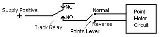
In the above circuit, the power supply is only connected to the points lever when the track section is clear (the track relay is on). This prevents the points running when a train is in the section. The points lever then selects either the normal control line or the reverse control line and controls the points.
Panel Track Indications
Another way the track relays are used at DVR is for the track diagrams in each signal box. The track diagram shows the layout of the track, signals, points and other items. Each track section on the diagram has a small indicator light mounted in the panel. The lights are controlled by the track relays for each section. The relay contacts switch the power to the lights. This enables the signalman to 'see' where the trains are on the track. There are two different methods used to indicate a trains presence in a track section. One method has the track section light turn on when the section is occupied (and off when the section is clear). The other method is the reverse - with the light being on when the track is clear and turning off when the section is occupied. Both methods are prototypical of the Victorian Railways. The second method is more 'fail-safe' because it prevents a train from 'hiding' in a section with a failed indicator light.
Level Crossing and Approach Indicators
Two other uses of track relays are the level crossing and approach indication circuits. The bells and lights in a level crossing circuit are turned on by the track relays of the track
section on the level crossing as well as the section approaching it. When a train nears a level crossing, the track relay for the approaching section turns off and powers the bells and
lights. The bells and lights don't turn off until the entire train exits the section on the level crossing - regardless of how long the train is.
An approach indicator is used in signal boxes to warn the signalman of trains approaching his/her signalling area. It is usually a bell or buzzer and an associated light.
Several different approach indicators might be situated in the same signal box - one for each line approaching the area. These indicators are powered via the approaching
track sections' track relays. When a train enters an approaching section, the corresponding approach indicator activates.
Disadvantages of Track Circuits
Track circuit systems are a very simple - in installing and maintaining. They do, however, have some downfalls.
- Because the system relies on electricity passing between the trains' wheels and the rail, rust on the surface of the rails can cause a problem. Very bad rust will prevent the current flow through the axles and therefore the system will not be able to detect a train. Note that for rust to cause a problem, it must affect each axle of the train. Normally, even on a very rusty track section, with a reasonable length train, at least some of the wheels are making good contact with the rail.
- If the wire connecting the earth rail to the circuitry is broken, or if the earth rail itself looses electrical contact at some point in a section (like at a fish plate), the portion of the section which is no longer earthed will no longer be able to detect trains. This is unlikely due to the strong connections used. Note that if either of the wires connecting to the ends of the positive rail is broken, the system will detect a train in the section even if there isn't one. This is less of a problem because it is 'fail-safe'.
Definition of 'Fail-Safe'
A 'fail-safe' system is one which, by virtue of its design, will fall into a 'safe' state if it fails. It does not mean the system will not fail or be faulty. Rather, it means that when the system
does fail (it is always assumed to fail at some point in time), the failure will not cause an unsafe state to exist.
An example is the simple controlled signal circuit. If the track circuit relay fails, it will fail in its off state (this is an accepted fail state of a relay that is used within its
allowed limits). The relay being off will keep the signal at red. If the control switch fails by not making a connection, either the red light will not work, or the green light will
not work. A signal with no lights showing it regarded by our operating rules as being at 'stop'. If any of the wiring associated with the signal breaks, once again one of the lights
will not work. A failure in the circuit will not cause the signal to go green. This would be called a 'wrong-side failure'. The only exception to this is failure of the earth rail in
the track circuit, which, as explained above, is unlikely.
All of the interlocking systems at DVR are designed to be fail-safe. If something goes wrong, it will usually only result in a signal not clearing to 'proceed' or being unable to change
points remotely. These are fail states that are preferable to signals being green with a train in front of them or points changing under trains.
Advantages of Track Circuits
- Simple circuit - requires only a relay, a ballast resistor an connections. The power supply is shared between all track circuits (up to a limit).
- Inexpensive and easy to install. Track connections are simple compared with single-point detection systems.
- Very reliable - relays and ballast resistors have large life-ps.
- Is virtually 'fail-safe'.
- Is the basis of more complicated signal interlocking systems that would otherwise be unreliable.
AC Track Circuits
A variation of the DC track circuits described above is the AC track circuit, also used at DVR. The idea is exactly the same except for:
- The power supply is 12V AC (alternating current).
- The track relays have a bridge rectifier and filter connected to them.
For more information about AC track circuits, please read this document